TXT 4.0 Controller
• 8 Universal inputs
• 4 Counting inputs
• 4 Motor outputs, alternatively 8 individual outputs
• 3 Servo Outputs
• Touch Display
• 2 6-pin sockets for connecting additional 3.3V I²C sensors
• Programming can be done both graphically and with Python using Robo Pro Coding software
Overview of Connections
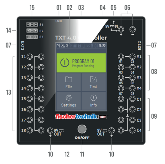
01 USB-A port (USB1)
02 Touch display
03 Micro SD card slot
04 Mini USB port (USB2)
05 9V IN, DC port
06 9V IN, Battery Pack connection
07 EXT connections for expansions
08 Outputs M1–M4 or O1–O8
09 Inputs C1–C4
10 9V Out
11 On / off switch
12 Speaker
13 Universal inputs I1– I8
14 Outputs S1–S3 for servo motors
USB-A port (USB1)
USB 2.0 host connection, for instance for fischertechnik USB camera art. No. 152522 or USB stick.
Touch Display
The color touch display shows the status of the Controller, which programs are loaded, and where the user is in the menu. Functions and programs can be selected, activated or deactivated. The user can display the values of variables or values from analog sensors while a program is running. A helpful menu overview is provided in the “Settings (Menu overview)” section. Swipe gestures are supported.
You can use the blocks in the Display category to design the screen of the TXT 4.0 Controller and make it easier to use. This requires two steps in ROBO Pro Coding App:
-
Configure, which means
• open a new file in the Display category using the Pages symbol with the plus sign at the top left
• drag the desired items to the screened area (this represents the configurable part of the display)
• adjust the specifications as needed. -
Program, which means
• program the interactions with the display in the main program using the blocks in the Display category.
Micro SD card slot
A Micro SD card fits in this slot (not included in the scope of delivery) to expand the device memory.
Mini USB port (USB2)
The USB 2.0 port (1.1 compatible) connects to the PC. A cable of this type is included.
9V IN, DC port (3.45 mm, plus pole internal)
The power supply from the Power Set is connected here (not included in the scope of delivery).
9V IN, Battery Pack connection
This connection allows for a mobile power supply via the fischertechnik Battery Pack (not included in the scope of delivery) as an alternative to the power pack.
EXT connections for expansions
These connections can be used to link additional ROBOTICS TXT 4.0 Controllers, thereby expanding the numbers of inputs and outputs. In addition, you receive an I2C interface, for instance for sensors.
Outputs M1– M4 or O1– O8
4 motors can be connected to the outputs. Alternatively, 8 LEDs or electromagnets with the second pole connected to a ground connection (⊥) can be used.
Inputs C1– C4
Fast counting inputs, record counting pulses up to 1 kHz (1000 pulses / sec.), for instance from fischertechnik encoder motors. These can also be used as digital inputs, for instance for buttons.
9V Out
Supplies sensors with the required operating voltage 9V+, such as color sensors, track sensors, ultrasound sensors, magnetic encoders.
On / off switch
Switches the Controller on or off, and indicates the operating status via different colors.
Speaker
The speakers can be used to play sounds or noises stored on the Controller or the memory card.
Universal inputs I1– I8
These signal inputs are designed for all-around use. They can be set using the ROBO Pro Coding software for:
• Digital sensors (buttons, reed contacts, phototransistors) – Digital 5 kΩ
• Infrared track sensors – Digital 10V
• Analog sensors 0–5kΩ (NTC resistors, photoresistors, potentiometers)
• Analog sensors 0–10V (color sensors) display the value in in mV (millivolt)
• Ultrasound distance sensors
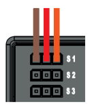
Servo connections S1-S3
3-Pole header to connect the fischertechnik servo 132292 or 203659. Ensure correct polarity!
Switching the Controller On and Off
Switch On Process
To activate the Controller, press the ON/OFF button (11) and hold it down for approx. 4 seconds until the display lights up – see number 11 in the section “Overview of connections.” Once the boot process is completed (indicated by a loading bar shown on the display), the main menu will appear.
Switch Off Process
To deactivate the Controller, press and hold the ON/OFF button (11) for approx. 3 seconds, until the button is illuminated red. Now, release the ON/OFF button and the Controller will be switched off. After switching off the Controller, unplug the power supply from the outlet.
Status Bar
The status bar at the top of the display contains display elements. The first four symbols show the statuses of the data connections. If the symbols are visible, the connection is active.
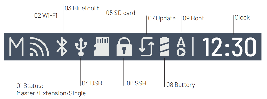
- TXT role: Master / Extension / Single
Master: The Controller as the master receives control commands from the PC and transmits them to the extensions.
Extension: The Controller receives control commands only from the master.
Single: In this mode, using the CAN interface to connect additional TXT 4.0 Controllers as expansions is not supported, in order to reduce power consumption.

- Wi-Fi/Client mode: activated / deactivated / connection error / Access Point mode / connected to the internet

- Bluetooth: activated / deactivated / connected / not connected

- USB Host: connected / not connected / USB stick connected / camera connected

- SD Card: inserted / not inserted / boot from the SD card

- SSH: activated / deactivated
- Update: current version is installed / status unknown / update successful, restart successful / failed / update available / update process running

- Power source Power supply/Battery Pack

- Boot: Autoboot deactivated / activated

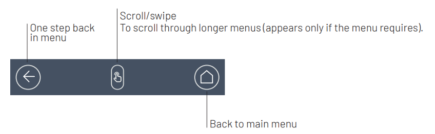
Control Elements
The user can navigate through the menu by touching the control elements.
Main Menu
Start the Program
The selected program is started. If no program is selected, a blue bar appears. After the program is started, the display switches to green. If the program is stopped, the bar is red.

File
If program files have been transferred to the Controller via download from a PC, they are listed here. They can be selected, assigned start functions, or deleted (see Main menu | File | File name).
If the user selects the example object, they will access the directory containing the executable Python file (name.py).

If the user clicks the file name, the “Load” button will turn green and the program can be loaded. If the user presses the arrow beside the program name, they will see the following options:

• Load
If this function is activated, the program is loaded into the program memory and can be launched by pressing the Start button in the main menu.
• Auto load
If this function is activated, the program loads automatically into the program memory once the power supply is switched on, and can be launched by pressing the Start button in the main menu.
• Auto start
If this function is activated, the selected program will start automatically once the power supply to the Controller is switched on.
• Delete project
The project is deleted (a security question will appear first).
Setting
• Role
Here, the Controller is assigned the role of Master or Extension.
Single / Master / Extension: 1…9
After a new Extension is connected, the Controller must be restarted to detect all extensions during the boot process.
• Language
The menu language can be changed here.
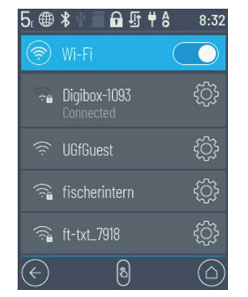
• Network
Wireless connections can be activated and deactivated here. In addition, the pairing code for Bluetooth and the network security key for Wi-Fi required to connect to the PC are displayed here.
o Wi-Fi: On / Off
Switch Wi-Fi on or off and connect to a router.
o Access Point: On / Off
Switch Access Point functions on or off. The network security key/SSID is displayed.
o Bluetooth: On / Off
Switch Bluetooth functions on or off. The pairing code is displayed.
• API key
Display the API key that must be entered to connect to the Controller.
• Date and time
The time, date and time zone can be set here.
• fischertechnik Cloud
Link to the fischertechnik Cloud. A pairing code is displayed that must be entered in the fischertechnik Cloud (www.fischertechnik-cloud.com).

• Updates
Complete operating system updates for the controller if necessary, when connected to the internet. The status bar indicates whether there are updates available.
• Energy management
Start the Controller up automatically when connected to the power supply, and adjust the display brightness.
• Remote access
Switch the SSH connection on or off.
Test
• Touch
Test the touch function.
• Sound
Test Calls up a display where available sound files can be selected and played.
Info
This option opens an info window displaying key details about the Controller, including its serial number (TXT UID), hardware version, and software version. It also shows the Controller’s Wi-Fi address, Bluetooth identification code, available user memory, and any installed licenses.
Extensions (EXT Connection)
Connect Additional TXT 4.0 Controllers
The 6-pole header “EXT1” or “EXT2” can be used to connect additional ROBOTICS TXT 4.0 Controllers.
This expands the numbers of inputs and outputs.
• Connect supply of electricity via the Power Supply or Battery Pack.
• The new Controller can be assigned the function of an Extension (1E-9E) using the display.
• This setting can be changed in the settings | Role | Extension menu.
• Connect the Controllers to one another using the included ribbon cable. Then, the status bar for the Controller will display whether it is a Master (M) or Extension (E).
When an Extension is connected to the Master, the Master must be rebooted before it will detect the Extension.
Each Extension 1E-9E may be used only once.
I2C Port
This standard port is designed for components available on the market that use this port, such as specialized sensors like the fischertechnik environmental, combination or RGB gesture sensor.
Connect to the Microcontroller
In general, the following options are available to connect to the Controller:
USB, Wi-Fi / Access Point, Bluetooth. This allows for connection to a PC (Windows or Linux), Mac, Android or iOS tablet or smartphone. The connection to Android or iOS is completed on the tablet/smartphone by selecting the Controller in the “Settings/Wi-Fi or Bluetooth” menu (iOS) or “Settings/connections/Wi-Fi or Bluetooth” (Android).
Note: The range is approx. 10 m, and is dependent on the quality of the USB/Wi-Fi stick used, as well as on ambient conditions (interference from other devices, obstacles in the room). Due to the limited bandwidth, restricted data processing should be expected when using a Bluetooth connection. The available bandwidth is significantly higher via Wi-Fi, and therefore the image transmission quality is better. The highest bandwidth, and therefore the best quality for image data transmission, is provided via a USB cable.
Connecting the TXT 4.0 Controller Via a USB Cable
- Connect a mini-USB cable to the PC and Controller TXT 4.0
- Plug the power supply into the outlet (or connect the Battery Pack)
- Plug the DC plug of the power supply into the 9 V IN input port (5) on the Controller
- Turn on the Controller using the on / off switch (11). Hold the switch down for approx. 3 seconds until the display is illuminated
Connecting the TXT 4.0 Controller with a PC Via Wi-Fi (with Router)
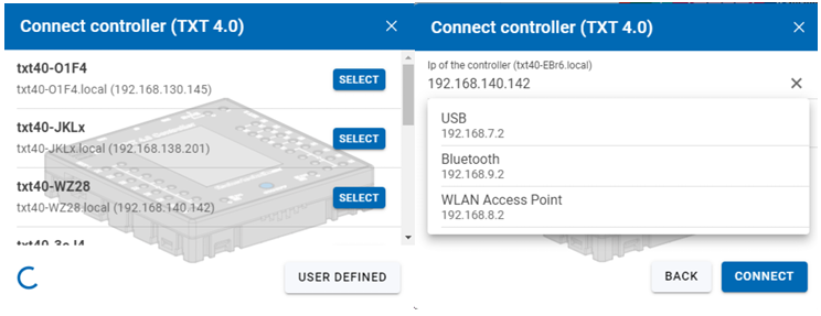
• Select the appropriate SSID / Wi-Fi network in Settings / Network / Wi-Fi. Then, enter the network key and “Connect.”
• To connect from a PC to the Controller in the same Wi-Fi network, enter the IP address of the Controller (INFO / WI-FI / IP ADDRESS) and the API key (SETTINGS / API KEY) in the Robo Pro Coding software.
• In the Robo Pro Coding software (click on “User Defined” button if you don’t see the below pop-up):
Connecting the TXT 4.0 Controller with a PC Via Wi-Fi (as an Access Point)
-
The ROBOTICS TXT 4.0 Controller must be switched on and Access Point must be active in the Settings menu under Network (see the section “Menu in detail”).
-
To connect to the ROBOTICS TXT 4.0 Controller, click the network symbol shown in the symbol bar at the bottom right of the PC screen.

- Select TXT4.0-…. and then click “Connect.”
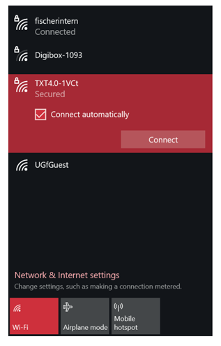
- Then, the network security key must be entered. This can be read off from the Controller display under Settings – Network / Access Point / Passphrase.
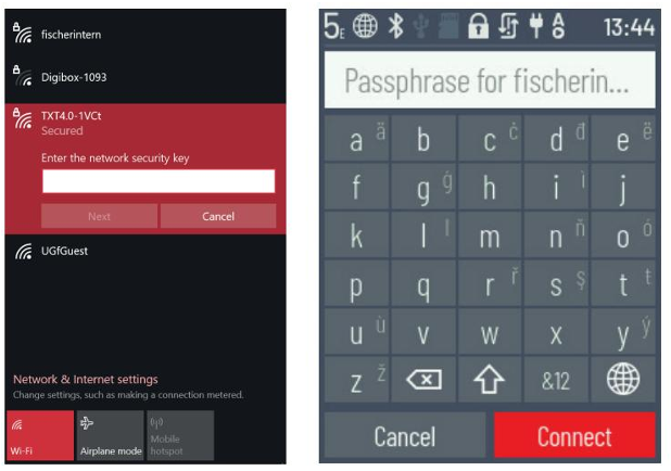
- Press “Next” to confirm, and the connection will be completed. If the user then clicks the network symbol once again, the following window will show the connection is complete and the device can be used.
Note: The window in which the Wi-Fi connection is completed can also be accessed via: Windows start button → Network and internet settings → Connect to a network. The windows and symbols may look slightly different in different operating systems. This manual uses the display in Windows 10.
Connect the TXT 4.0 Controller to a PC Via Bluetooth
-
The ROBOTICS TXT 4.0 Controller must be switched on, and “Bluetooth” must be active in the menu under the “Network” selection (Settings / Network / Bluetooth).
-
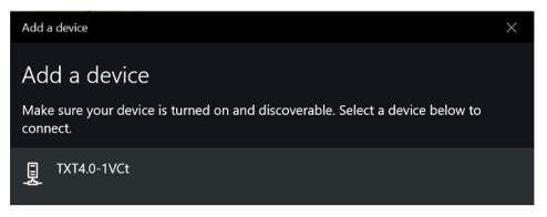
To complete the Bluetooth connection to the ROBOTICS TXT 4.0 Controller, select the Windows start button on the PC screen and then select Bluetooth & other devices. A new window will appear. In this window, click Add Bluetooth or other devices. Then, select Bluetooth.

- All visible devices will be displayed, including the ROBOTICS TXT 4.0 Controller. Double click the TXT 4.0 Controller to select it.
- A new window will appear requesting a pairing code or a pin. The pairing code / PIN is available on the Controller TXT 4.0 under “Network / Bluetooth / Pairing code.” Click Connect.

- In the Windows menu, click “Connect using:” and then “Access point” to activate the Bluetooth connection.
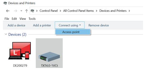
Note: This step must be completed each time the PC or the TXT Controller are switched off and back on.
- Now, Bluetooth can be selected as the connection in the Connection menu of the Robo Pro Coding software (see Wi-Fi connection).
Updating the Operating System
The Linux operating system of the TXT 4.0 Controller must always be kept up to date. This provides ongoing access to new functions, and ensures the security of the operating system.
• To complete an update, the TXT 4.0 Controller must be connected to the internet via Wi-Fi. To do so, select the appropriate SSID / Wi-Fi network in Settings / Network / Wi-Fi.
• Then, enter the network key and connect. The status bar indicates whether the Controller is connected to the internet, and whether an update is available (see the section “Menu in detail” / Status bar).
• If an update is available, the newest available version is displayed (such as Release 3.1.0) in Settings / Updates under “Online updates.” Select the newest version and press “Installation.” The installation will be completed.
• This process will take several minutes. Then, the Controller must be switched off and back on again manually.
• An update can also be completed via a USB stick or SD card (not included in the scope of delivery), even if the Controller is not connected to the internet.
• The file required for this process and instructions are available for download from the internet at
www.fischertechnik.de/TXT40Controller
Technical Data
• DIMENSIONS AND WEIGHT
90x90x17.5mm (LxWxH), 110g
• MEMORY AND PROCESSOR
512 MB DDR3 RAM, 4 GB eMMC, Micro SD card slot (memory card not included)
ARM(R) dual Cortex-A7, 650 MHz + Cortex(R)-M4; programmable with ROBO Pro Coding
Software, Python or C-Compiler (not included)
• OPERATING SYSTEM
Linux-based, open-source incl. Linux camera driver, image processing software integrated into
Robo Pro Coding.
• POWER SUPPLY (NOT INCLUDED)
Via Battery Set (8.4 V 1800 mAh) or Power Set (9 V / 2500 mA)
• PORTS
USB 2.0 Device: Mini USB port USB 2.0 Host: USB-A port
Wireless port (2.4 GHz / range approx. 10 m)
Bluetooth/Wi-Fi: 5.0 (BR, LE & EDR) / Dual band 2.4GHz and 5GHz, 802.11 a/b/g/n
Expansion ports: EXT header 6-pole; I2C
Pin Assignment EXT1+EXT2:
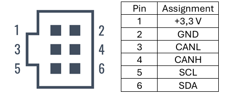
Note: All cables work with 3.3 volts. External voltages greater than 3.3 volts may damage the device!
• Signal Inputs and Outputs
8 universal inputs: Digital, analog 0 – 9 V DC; analog 0 – 5 kΩ
4 fast counting inputs: Digital, frequency up to 1kHz
4 motor outputs 9 V/250 mA: Speed continuously adjustable, short circuit resistant,
alternatively 8 single outputs.
3 servo connections:

Sound output: .wav Files via speaker
• TOUCH DISPLAY
2.4” TFT, 320x240 Pixel, 65536 colors
Note: Do not allow sharp or pointed objects to come into contact with the touch screen, as this may
cause damage!