Introduction
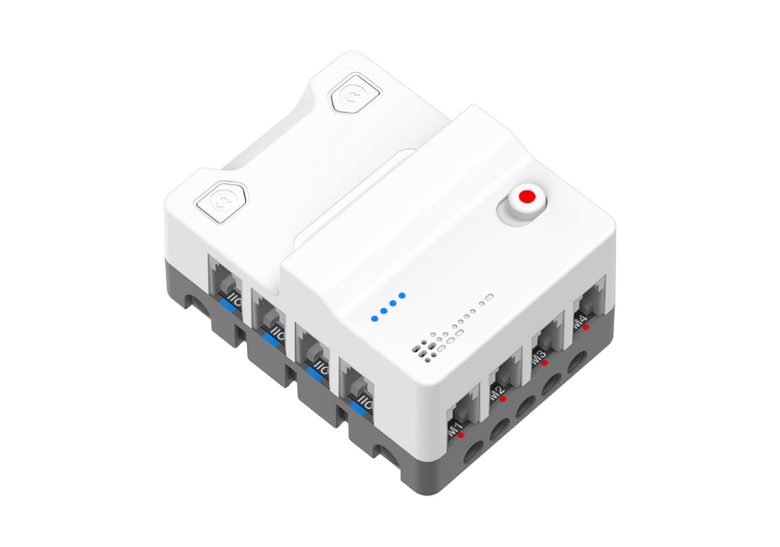
The Nezha Pro Breakout Board is a Micro:bit expansion board designed for education and creative programming, aiming to stimulate students' innovative thinking and hands-on skills. It not only integrates two convenient motor control buttons and a 4-way motor driver, but also comes with an 8-way sensor expansion port, providing students with a versatile platform for experimentation and exploration. These motor control buttons allow direct control of the motor's direction of rotation without connecting the Micro:bit, increasing flexibility of operation. All interfaces use RJ11 connectors with a dud-proof, anti-reverse plug design to ensure fast and accurate connections. The case of the expansion box is specially designed with interfaces that are compatible with LEGO and Fischertechnik building blocks, supporting students to combine electronic modules with mainstream building blocks to build personalized creative programming creations.
Characteristics
- Independent Motor Control
- RJ11 port design
- Colour recognition system
- Support for closed-loop motors
- Compatibility design
- Slide Power Switch
Technical Specification
| Item | Parameter |
|---|---|
| Name | Nezha Pro Breakout Board |
| SKU | EF05070 |
| Dimension | L80mm (Not include the Micro:bit) x W60mm x H44mm |
| GW | 142g (Not include the Micro:bit) |
| Charging Voltage | 5V |
| Charging Current | 3A |
| Charging Time | 50min |
| Battery Capacity | 900mAh / 6.6Wh |
| Max. Working Voltage | 8.4V |
| Rated Working Voltage | 7.4V |
| Min. Working Voltage | 6.4V |
| Standby Current | 0.01A |
| Micro:bit Supply Voltage | 3.3V |
| Motor Output Working Voltage | 6.4~8.4V |
| Motor Connection Rated Output Current | 1A |
| Motor Connection Max. Output Current | 2A |
| RJ11 Connection Output Voltage | 3.3V |
| RJ11 Connection Output Max. Current | 1.0A |
| Lasting Operation Time | 45min (Connect the AI Lens, 4 Smart Motors, 2 LED modules, there might be some difference because of the testing environment and so on) |
| Motor Connectors | 4 Units |
| Sensors Connectors | 8 Units |
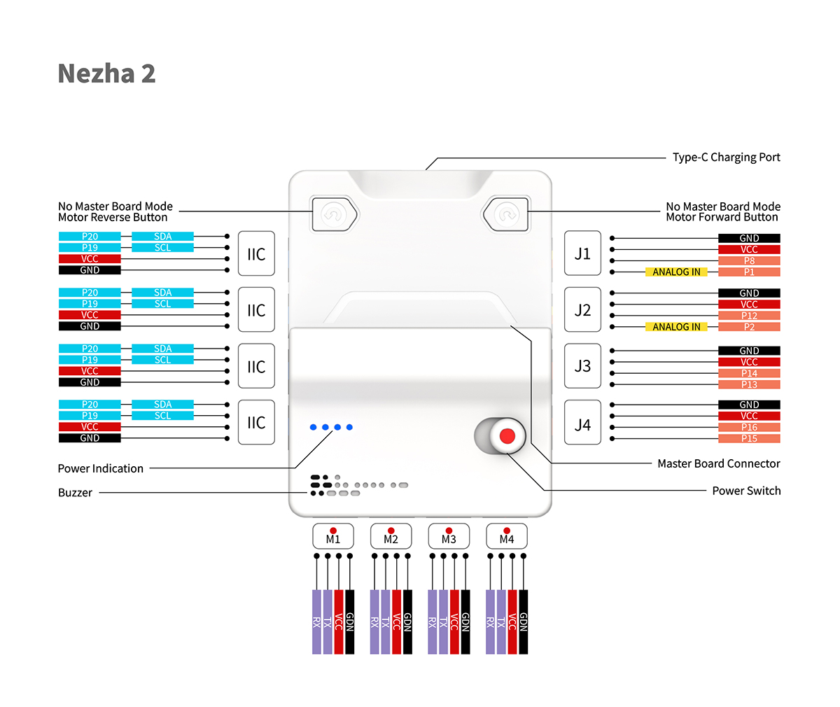
Introduction to Interface Pins
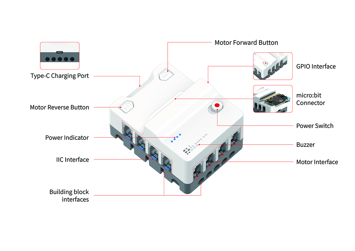
Introduction to Main Modules
Power Indicator
| Current Status | LED 1 | LED 2 | LED 3 | LED 4 | Battery Capacity |
|---|---|---|---|---|---|
| Discharging Status | On | On | On | On | 76% ~ 100% |
| On | On | On | Off | 51% ~ 75% | |
| On | On | Off | Off | 26% ~ 50% | |
| On | Off | Off | Off | 1% ~ 25% | |
| Charging Status | On | On | On | On | 100% |
| On | On | On | Flashing | 75% ~ 99% | |
| On | On | Flashing | Off | 50% ~ 74% | |
| On | Flashing | Off | Off | 26% ~ 49% | |
| Flashing | Off | Off | Off | 0% ~ 25% |
Programming Initialization
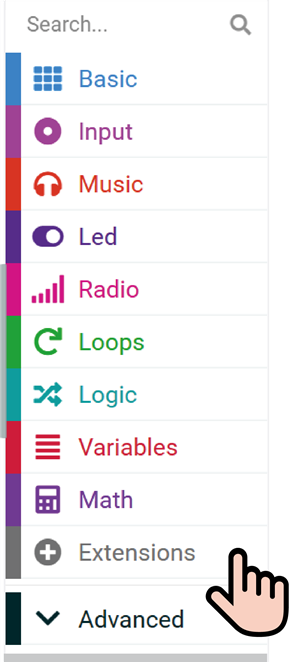
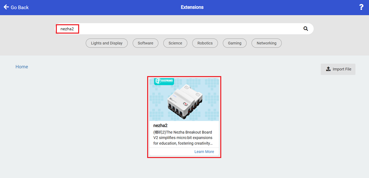
For programming Nezha Pro Breakout board, we need to add an extension. Click "Extensions" in the MakeCode drawer to see more choices.
Search with "nezha2" and have it downloaded.
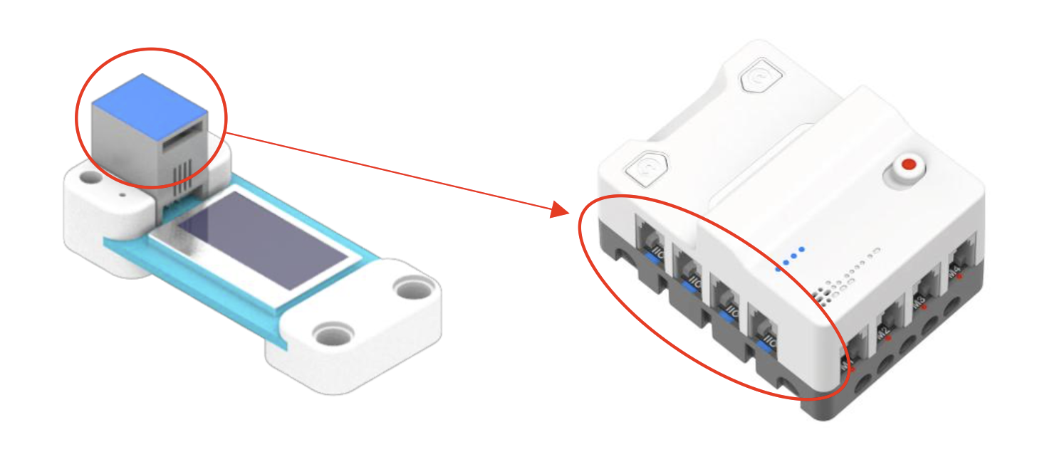
Interface Connectors
Each PlanetX sensor has a colour. Match it with the same colour on the Nezha Pro Breakout board. Use this table to see where to connect each sensor.
| Item | Colour | Connection Type | Connection port |
|---|---|---|---|
| Smart Motor | 🔴 | UART | M1, M2, M3, M4 |
| Sensor | 🔵 | IIC | IIC |
| Sensor | 🟡 | Analog GPIO | J1, J2 |
| Sensor | 🟠 | Digital GPIO | J1, J2, J3, J4 |